Introduction To CNG LPG Pressure Reducer
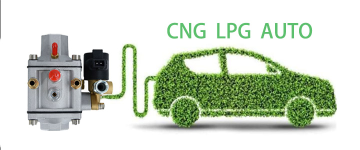
What is a pressure reducer£¿
The pressure reducer, which many driver friends have given it a loud nickname "airbag". Next, let's understand the working principle of this "air bag": the rated pressure at the inlet of the pressure reducer is 20Mpa, and the experimental pressure for the strength of the inlet joint is 7.5Mpa. When the inlet pressure is 2-20Mp, the pressure change after the first stage of pressure reduction is 0.5Mpa; After the second stage of pressure reduction, the pressure changes from 0.1 to 0.3 Mpa, with an allowable value of 0.02 Mpa. The opening degree of its valve port is automatically adjusted by the vacuum degree during engine operation, but the initial opening degree can be adjusted. When the pressure inside the gas cylinder is below 2Mpa, it can still supply gas to the engine normally. In short, 1 is stress reduction; 2 is voltage stabilization.

Important components of CNG pressure reducers
1. High pressure solenoid valve
Simply put, it is a shut-off valve. The high-pressure natural gas in the cylinder is transported through a high-pressure steel pipe to the pressure reducer, where it is controlled by a high-pressure solenoid valve. When the gas computer board collects relevant sensor signals and reaches the allowable gas transfer condition, the solenoid valve will open, and at this time, the high-pressure natural gas will enter the pressure reducer chamber (commonly known as gas transfer). When the gas transfer conditions are not met or the relevant sensors are damaged during use, the solenoid valve will immediately close to prevent high-pressure natural gas from continuing to enter the pressure reducer chamber (commonly known as not transferring gas), in order to avoid unnecessary danger.
2. Primary cavity
The high-pressure gas flowing out of the gas cylinder passes through the high-pressure steel pipe and high-pressure solenoid valve, relying on its own pressure to open the first stage valve, and flows into the first stage pressure reducing chamber through the gap between the first stage valve and the valve seat. During this process, the pressure of the high-pressure gas is significantly reduced. There are many baffles in the first stage pressure reducing chamber, and high-pressure gas is further reduced as it passes through them. As the amount of gas in the first stage pressure reducing chamber increases, the indoor pressure continues to rise. When the pressure reaches a certain value, the first stage diaphragm protrudes upwards, compressing the first stage spring. The first stage cylinder drives the first stage lever to move, reducing the opening of the first stage valve and reducing the entry of high-pressure gas. As the gas in the first stage pressure reducing chamber continuously enters the second stage pressure reducing chamber, the pressure in the first stage pressure reducing chamber decreases. When the pressure drops to a certain value, the first stage diaphragm is pressed down under the pre tightening force of the first stage spring. The first stage cylinder then drives the first stage lever to move, causing the opening of the first stage valve to increase, and high-pressure gas flows into the first stage pressure reducing chamber. In summary, the opening and closing of the first stage valve are determined by the position of the first stage diaphragm. Increasing the pre tightening force of the first stage spring, reducing the pressure in the first stage pressure reducing chamber, and increasing the pressure in the second stage pressure reducing chamber will all cause the first stage diaphragm to move downwards and increase the opening of the first stage valve; On the contrary, if the first stage diaphragm is moved up, the opening of the first stage valve will decrease.

3. Secondary cavity
The gas that has undergone initial pressure reduction in the first stage pressure reducing chamber enters the second stage pressure reducing chamber through the second stage valve. Due to the throttling effect of the second stage valve, the pressure is further reduced. As the amount of gas entering the second stage pressure reducing chamber increases, when the pressure in the second stage pressure reducing chamber exceeds the pre tightening force of the second stage spring, the second stage diaphragm protrudes upwards, compressing the second stage spring and driving the second stage lever action through the second stage cylinder, reducing the opening of the second stage valve and reducing the amount of gas entering. As the gas in the second stage pressure reducing chamber is continuously discharged (entering the low-pressure delivery pipe through the outlet and entering the spray rail), the pressure in the second stage pressure reducing chamber decreases. When the pressure is less than the pre tightening force of the second stage spring, the second stage diaphragm is pressed down due to the pre tightening force of the second stage spring. The second stage cylinder drives the second stage lever to move, causing the opening of the second stage valve to increase, and the amount of gas entering the second stage pressure reducing chamber begins to increase again. The opening and closing of the secondary valve are controlled by the secondary lever, and the action of the secondary lever is determined by the position of the secondary diaphragm. The position of the secondary diaphragm is determined by the pressure of the secondary pressure reducing chamber, the pre tightening force of the secondary spring, and the demand for the spray rail.
4. Safety valve
The safety valve can ensure the safety of the pressure reducer, and it is designed with a spring type automatic exhaust and pressure relief method. The safety valve includes the valve body, regulating plug, spring, valve core, gasket, and other parts. It is assembled and installed at the side pressure port of the first stage pressure reducing chamber, ensuring that the air pressure in the first stage pressure reducing chamber does not exceed 1.3 times the rated pressure, which is 0.65Mpa. When the pressure exceeds this, it is commonly known as "safety valve leakage". At this time, it is necessary to check whether the excessive wear of the first stage valve core caused by prolonged use has led to air leakage in the first stage chamber

The pressure reducer is a core component, and its performance, mechanism, and characteristics directly affect the performance of the engine.
1. The situation that requires emphasis on both power and gas consumption.
2. Having a testing report from a national professional testing institution.
3. The price of the pressure reducer and our company's reputation and after-sales service system.
4. Technical information and maintainability of pressure reducers.
5. Choose an engine model that is suitable for natural gas modification of automobiles, and it is best to have supporting test results.
6. Adapt to the usage of oil to gas vehicles and the main operating range of the engine.
7. Choose to adapt to the local climate conditions.
8. The lifespan of the pressure reducer and the quality of its components.
 Refer to£ºhttps://en.wikipedia.org/wiki/Pressure_regulator
The pictures and articles are from the internet. If there is any infringement, please contact us to delete them.
Popular articles
-
Advantages Of CNG Gas V
Compressed natural gas vehicles are vehicles th
-
How the CNG Automotive S
Compressed natural gas (CNG) automotive systems
-
What Is CNG Pressure Red
The pressure reducer of natural gas vehicle is
-

Advantages And Principle
LPG and CNG are two mainstream alternati
-
Differences Between Sing
Characteristics of Gas Single Point Device
-
Reasons For High Gas Con
1. Original vehicle condition A. The tec
-

How To Improve The Power
1. Install ignition advance angle What i
-

How The CNG Gas Vehicle
If you want to know ¨C how does the CNG conversi


Latest comments
0piece comment
no comments, welcome to comment¡£